Overview
As the site has no mains connection it relies on a battery bank charged by solar panels and a wind turbine. Currently there is no GPS system for frequency or time reference. The old exciter was liable to drift and was replaced in Feb 2017 with this system. It was important to minimise the dc power requirement. The current requirement of the complete exciter at 12v is 180mA for 17dBm output.The ADF4351 synthesiser is controlled by an Arduino Nano processor, together with a 10MHz OCXO and a keyer module. The ADF4351 was purchased from SV1AFN through his website here. Chinese versions are available on eBay at similar prices.

Block diagram
can be found here
The dc power is first reduced to 8V in a dc-dc converter (eg this one). 8V feeds the Arduino with its internal regulator, the keyer and the LNA amplifier. A 5V regulator feeds the OCXO and a 3.3V regulator for the ADF4351. I used a level converter to interface the 5V levels to 3.3V for the ADF board.
Hardware connections
Three connections are needed between the Arduino and the ADF board:-| Arduino pin* |
SV1AFN board pin |
ADF4351 pin |
| 10 |
3 |
3 LE |
| 11 |
4 |
2 DATA |
| 13 |
1 |
1 CLK |
* as defined in the Arduino sketch used.
ADF4351 registers
Initially I tried using the register values to change frequency, wanting a 400Hz FSK. But the spectrum showed significant "key clicks" or splashes of energy each time the frequency was updated by the Arduino. So to improve on this, the Arduino was programmed to simply provide a fixed frequency from the 4351. The FSK was then generated by shifting the OCXO frequency slightly. This means that machine generated modes such as PI4 or JT65 are not available.I used the software provided by Analog Devices to generate the register values. The input parameters to the software were
RF 1296.87
channel spacing 1kHz
ref frequency 10MHz
R counter =2
prescaler = 8/9
feedback signal = fundamental
low spur mode = yes
digital lock detect = yes
double buff = no
charge pump current = 5.00mA
LDF = FRAC-N
RF output - enabled
Aux o/p power = -4dBm
RF output power = +5dBm
channel spacing 1kHz
ref frequency 10MHz
R counter =2
prescaler = 8/9
feedback signal = fundamental
low spur mode = yes
digital lock detect = yes
double buff = no
charge pump current = 5.00mA
LDF = FRAC-N
RF output - enabled
Aux o/p power = -4dBm
RF output power = +5dBm
The register values created were:-
regs[0] = 0x10305D8;
regs[1] = 0x80087D1;
regs[2] = 0x78009E42;
regs[3] = 0x4B3;
regs[4] = 0x92803C;
regs[5] = 0x580005;
Arduino s/w and sleep modes
For the Arduino sketch I adapted some code from G8AGN who had in turn simplified original code written by F1CJN. My adapted code programs the ADF4351 with the register values and then puts the Arduino into sleep mode. This reduces its dc current from 27mA to 9.3mA.The sleep modes are described here
The relevant lines of code are
#include <avr/sleep.h>
set_sleep_mode(SLEEP_MODE_PWR_DOWN);
sleep_enable();
sleep_mode();
set_sleep_mode(SLEEP_MODE_PWR_DOWN);
sleep_enable();
sleep_mode();
OCXO
The OCXO is a 10MHz Micro Crystal 5v device available from a few suppliers on eBay for about £24. For this application it is ideal, having a very fast warm up and a steady state dc consumption around 80mA. Frequency adjustment is by voltage control.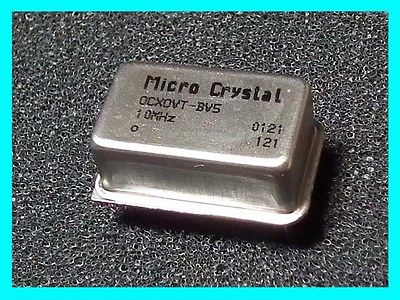
The schematic for the OCXO and keyer are shown here.
G4JNT keyer
This keyer is available from G4JNT. I bought the analog version which allows a code to be transmitted for (eg) 24v line monitoring.
I set up the analog input on the keyer so that it outputs a code in the range 0 to 255, allowing the 24V line to be monitored remotely. The input is scaled so that 255 is equivalent to 28.05V.
LNA4all amplifier
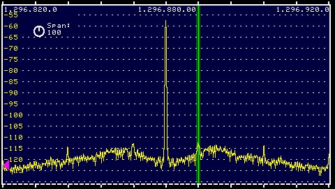
The LNA4all is designed as a low noise preamp but is used here for its good large signal handling and produces about 17dBm output.Phase noise measurements
The ADF4351 is not the best source for low phase noise but it is easily available! The measurement method used a Kuhne transverter from 1296 to 144MHz then an Anglian transverter from 144 to 28 where an Elecraft K3 and P3 produced the images below.The resolution bandwidth is span width/450, so for 100kHz span it equates to ~222Hz/pixel, so the noise at 10kHz offset for example looks like -57dB and to this we add 23dB to give -80dBc/Hz.
This is the 5kHz span spectrum and waterfall showing the 400Hz shift FSK.
