Overview
As the site has no mains connection it relies on a battery bank charged by solar panels and a wind turbine. This means that the DC to RF efficiency is important, and the old PA was very inefficient, producing about 10W from 65W input. A search for a better PA resulted in a decision to use the now rather old Mitsubishi module M57762, with better efficiency than the newer RA18H1213g.The M57762 data sheet claims 10Woutput at 1296MHz for less than 3A dc input. The device needs about 23dBm drive, and so an intermediate amplifier was used to raise the exciter output of 17dBm up to a suitable level. The amplifier chosen was the ADL5324 with a gain of about 14dB and P1 output of 27dBm. PCBs for this are available from W1GHZ.
The M57762 was built into an enclosure from PE1RKI who also supplies a suitable PCB. The enclosure was bolted to a large heatsink and equipped with a thermostatically controlled fan to improve long term reliability.
The new PA was installed on 24 Aug 2018. The total dc (including exciter) drawn from the 13.5v rail is 3.1A (fan off) and 3.3A (fan on).
Block diagram
can be found here
Fan control
The circuit is shown here. A temperature sensor (LM35DT) is bolted to the M57762 enclosure and feeds the CA3140 opamp. This drives a IRF510 mosfet switch to control the fan. A potentiometer sets the desired temperature for the fan to turn on, whilst the hysteresis is determined by the ratio of R1 and R2. The system has been set to turn on at 41C and off at 35C.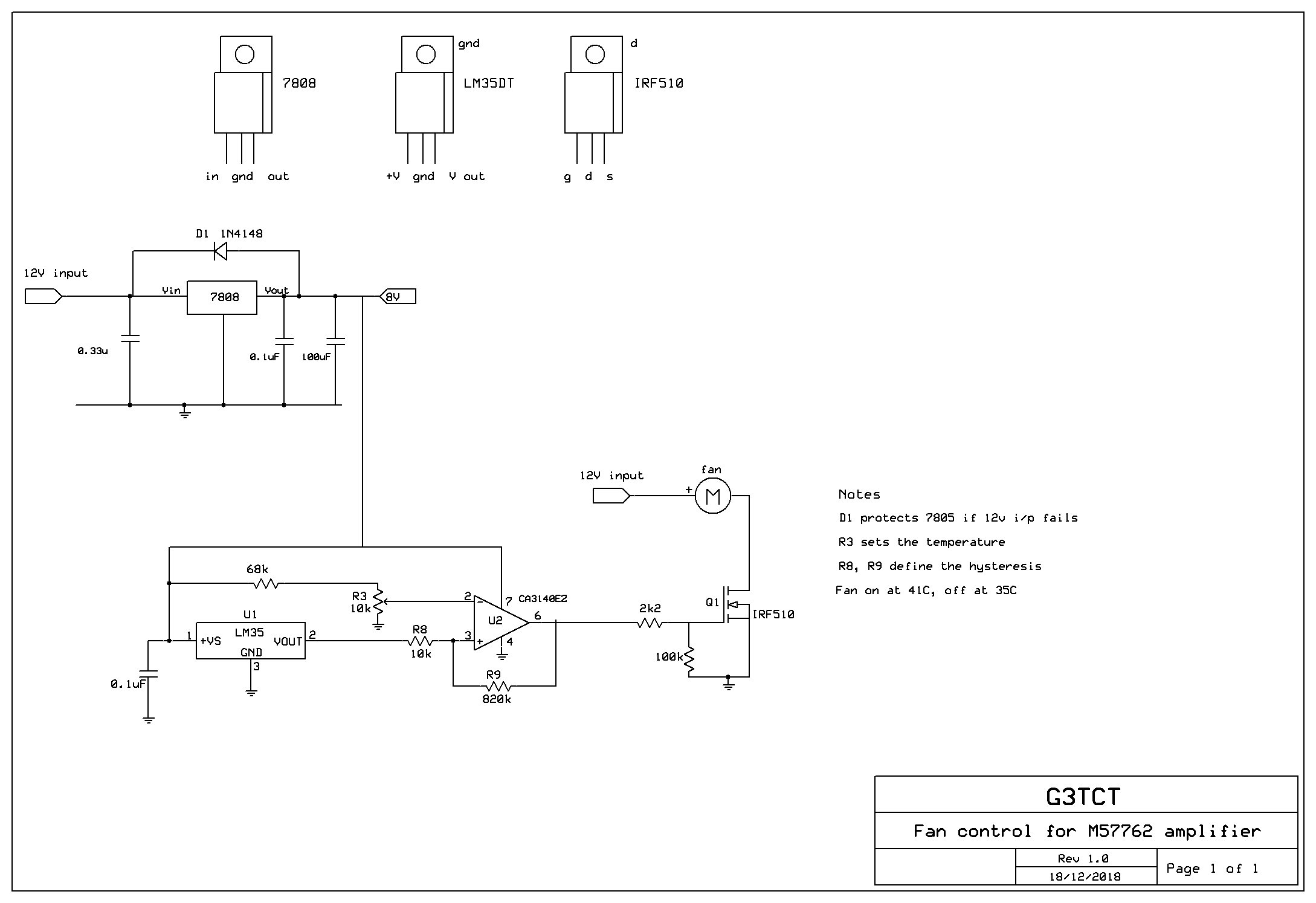
