Ref: P3 manual Rev C, page 22.
K3 f/w 4.51, P3 f/w 1.26
The Elecraft P3 is an SDR in its own right, capable of receiving signals between 450kHz and about 21.7MHz. Normally it is connected to the IF output of the K3 and tuned to the K3 IF of 8.215MHz. To monitor your own transmission, try the following:-
With K3 and P3 set up as normal, tune the K3 to the desired frequency (eg 21200kHz). Connect the K3 to a dummy load and set power to desired level. Disconnect the RS232 line from the K3, leaving the P3 connected to your computer (if you want to capture the images using the P3 utility).
Power down the P3 and then power it up again (this is necessary otherwise the P3 update rate is very slow). On the P3, tap Menu and select Xcvr Sel; select the last item in the list "0 Hz". The P3 frequency now reads the actual RF frequency and you can tune it by HOLDing the CENTER control on the front panel and then turning the knob. (You may have to change the "Center En" menu entry to "ON.") The tuning rate in CENTER mode is proportional to span. Set the span to maximum to tune quickly and then narrow the span to zero in on the signal. [Thanks to Alan N1AL for helpful comments on this use of the P3]
[An alternative method in Xcvr Sel is to select “USER”. Tap Menu again and select Xcvr Def. On the new page that appears, set Language to None, IF tuning to Not inverted, and the IF centre frequency to the desired frequency (eg 21200kHz, using Fn6 and Fn7). Tap Exit.
There is a bug/feature in the way the P3 responds to changes in the Xcvr Def window. If you set a new frequency for the IF and exit, nothing happens. But if you then select Xcvr Sel, and then select some other IF eg 455kHz and then select User again, the P3 then tunes to the defined frequency.]
Disconnect the IF input lead from the P3, and connect a short wire or a small whip antenna in its place.
CAUTION:
DO NOT connect the P3 to the transmitter output, it will damage the P3.
Be careful when the P3 is connected to anything other than the K3 IF out because the P3 IF input is not protected against static discharge. I would recommend putting a pair of back-to-back diodes in parallel across the input. If you don't want to modify the P3 you can solder the diodes to a BNC male connector and connect it and the antenna to the P3 using a BNC "T" adapter.
Select peak reading from the normal menu, select the desired span, ref level and set Scale to (eg) 80dB.
Switch to transmit with the K3 and adjust ref level if needed. In the P3 utility, click Capture Image and paste it to a suitable program eg Paint. You can then save the image.
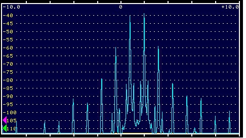
Here are some images I captured using a few seconds of speech with my normal settings on USB on 21.2MHz, 20kHz span and 80dB scale at 5, 25 and 95W.
First the 5W level:-
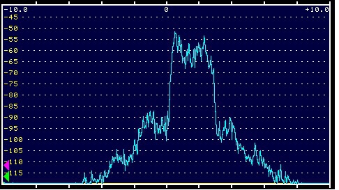
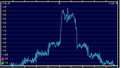
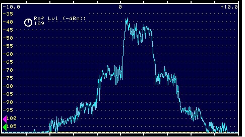
At the 5W level, the adjacent 2kHz splatter is about 30dB down; at 25W 35dB down, and at 95W it is about 27dB down.
Then 25W:-
Then 95W:-
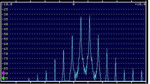
It's also possible to transmit a two tone signal using the K3 and here's the result I got at the 25W level:-
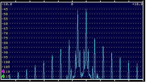
and the 95W level:-
4m PA output spectrum
I also wanted to look at the spectrum of my 70MHz PA. To do this I made a Butler crystal oscillator running on 50.95MHz (I happened to have a crystal in the junk box). The oscillator drives a SBL-1 type balanced mixer and the output of the mixer on 19.25MHz is then input to the P3, adjusted suitably. (The 3rd harmonic of the crystal will also allow measurement of 144MHz systems.)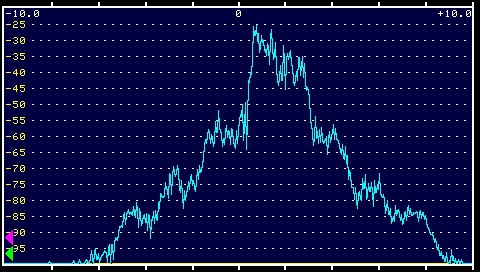 Here
is my 70MHz system with a few seconds of speech at 160W output (the
maximum). The ssb splatter in the adjacent 2kHz is about 25-27dB down at 160W output.
Here
is my 70MHz system with a few seconds of speech at 160W output (the
maximum). The ssb splatter in the adjacent 2kHz is about 25-27dB down at 160W output.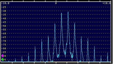
The 2 tone intermod is about 15dB down at 160W.
At 140W output, the 2 tone intermod improves to about 20dB down.
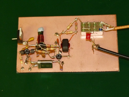
Butler oscillator and mixer. The schematic is here.