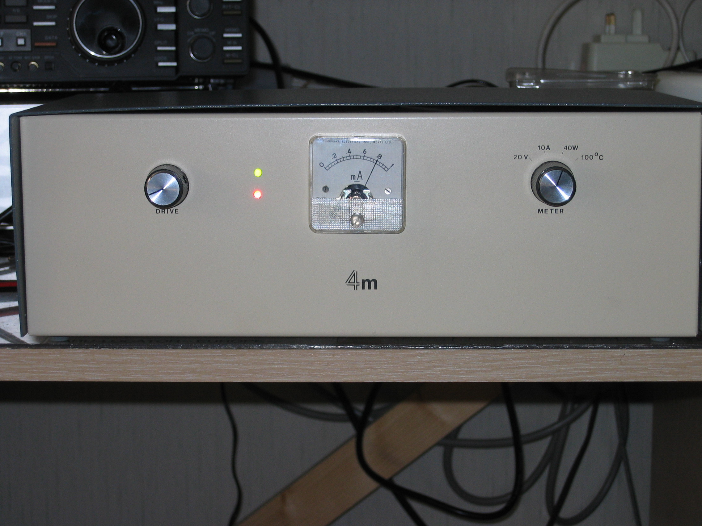
4m rig
On 4m I am currently running 160W out to a 6 ele DK7ZB antenna. The rig is an Elecraft K3 driving an OZ2M transverter which in turn drives a homebrew PA using the SD2931-10 device.What's wrong with FM? See here.
6m rig
On 6m I use the K3 either barefoot or through an Acom 1000. The antenna is a 5 ele M2.OZ2M transverter
This is a good design, definitely recommended, see full details here. There is a kit for the basic transverter developing about 100mW and also for a 25-30W PA using a Mitsubishi module. Alternatively you could buy the module in UK from GH Engineering and buy/build the rest from information on Bo's website (as I did).Here's a view of the completed transverter
and on the right an inside view. Click on the images to see them full size.
Here's the 25w PA before mounting the module
See this page for antenna changeover info.
I found the temperature stability of the crystal oscillator was not so good and I added a Kuhne crystal heater type QH40A. This has improved the stability a great deal and the drift of the whole system with my K3 is now less than 10Hz.

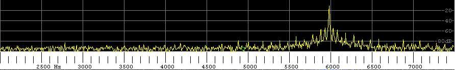
There is a concern that transverters using a 42MHz local oscillator can produce spurious emissions just below the 70MHz band. This arises from 3 x 42 =126MHz less 2 x 28 = 70. To test this, I set the transceiver to 28.001, and looked at the spectrum from 69.997 to 70.002. Any spurious should appear at 69.998.
The spectrum is shown below - 70.001 is rendered as 6000Hz. There is no sign of any signal on 3000Hz - a suppression of more than 80dB.
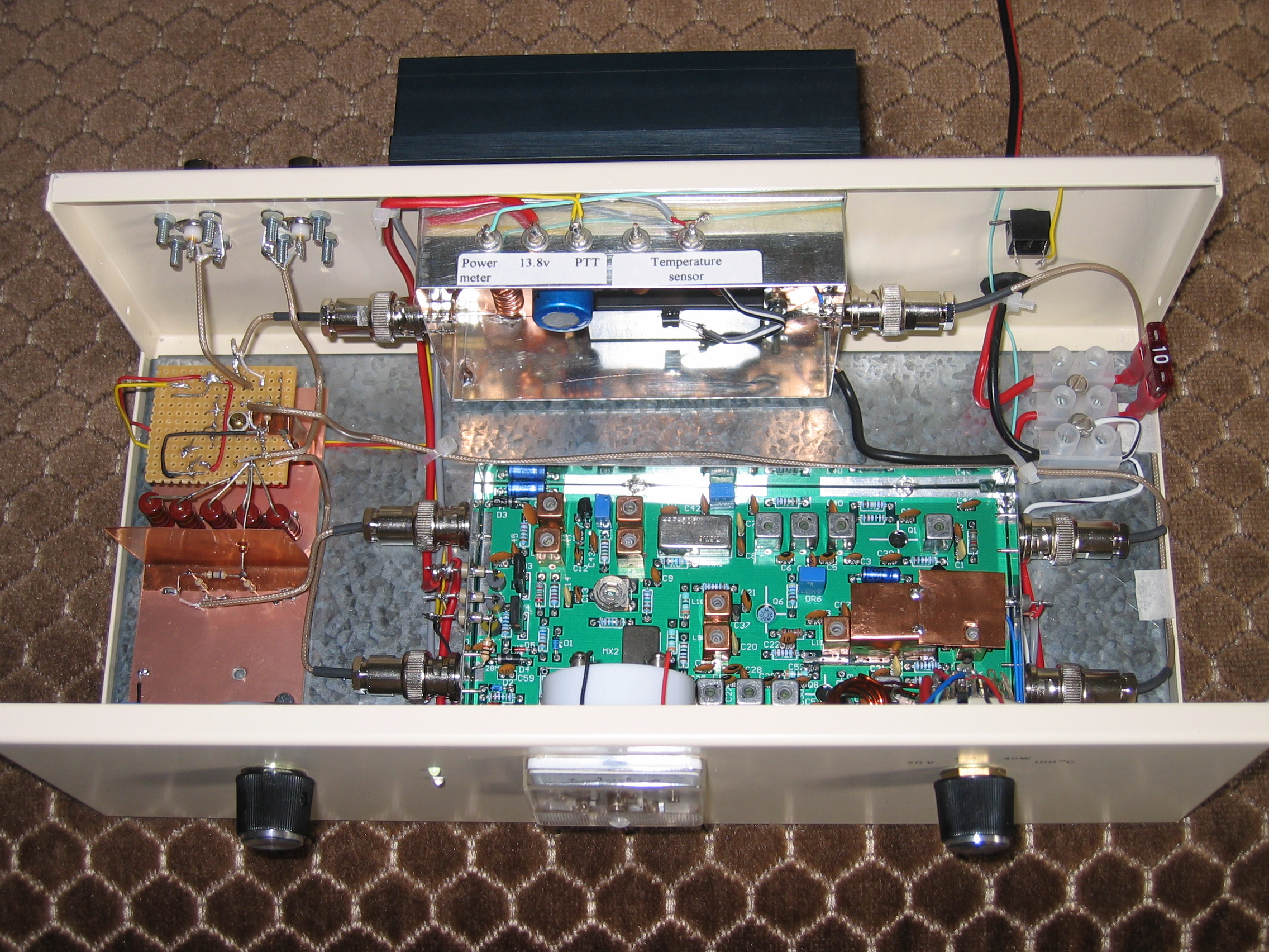
SD2931-10 4m PA
This was my second 4m PA project of recent years - the first used a dual MOSFET design.The SD2931-10 design was taken from (a) the GI0GDP article on the 4m website for a 160W PA, and (b) the article by EI9GQ in RadCom (Aug 2008 p22) for a 2m PA using the same device. These devices or near equivalents are available on eBay from time to time at reasonable prices. (I always felt very nervous about paying a lot for a device which could expire in a microsecond!)
(For more power see the info from ON5VW on a 600W PA for 6m using two SD2933.)
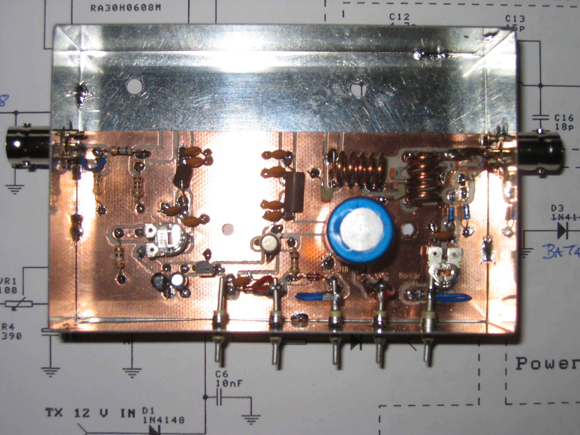
The datasheet shows the SD2931-10 typically produces150W output for 50v@4.6A dc input at 65% efficiency. It has about 0.5dB gain compression at 170W output. I built mine without making a proper pcb, but using double-sided board as shown.
NEW Output spectrum is shown here.
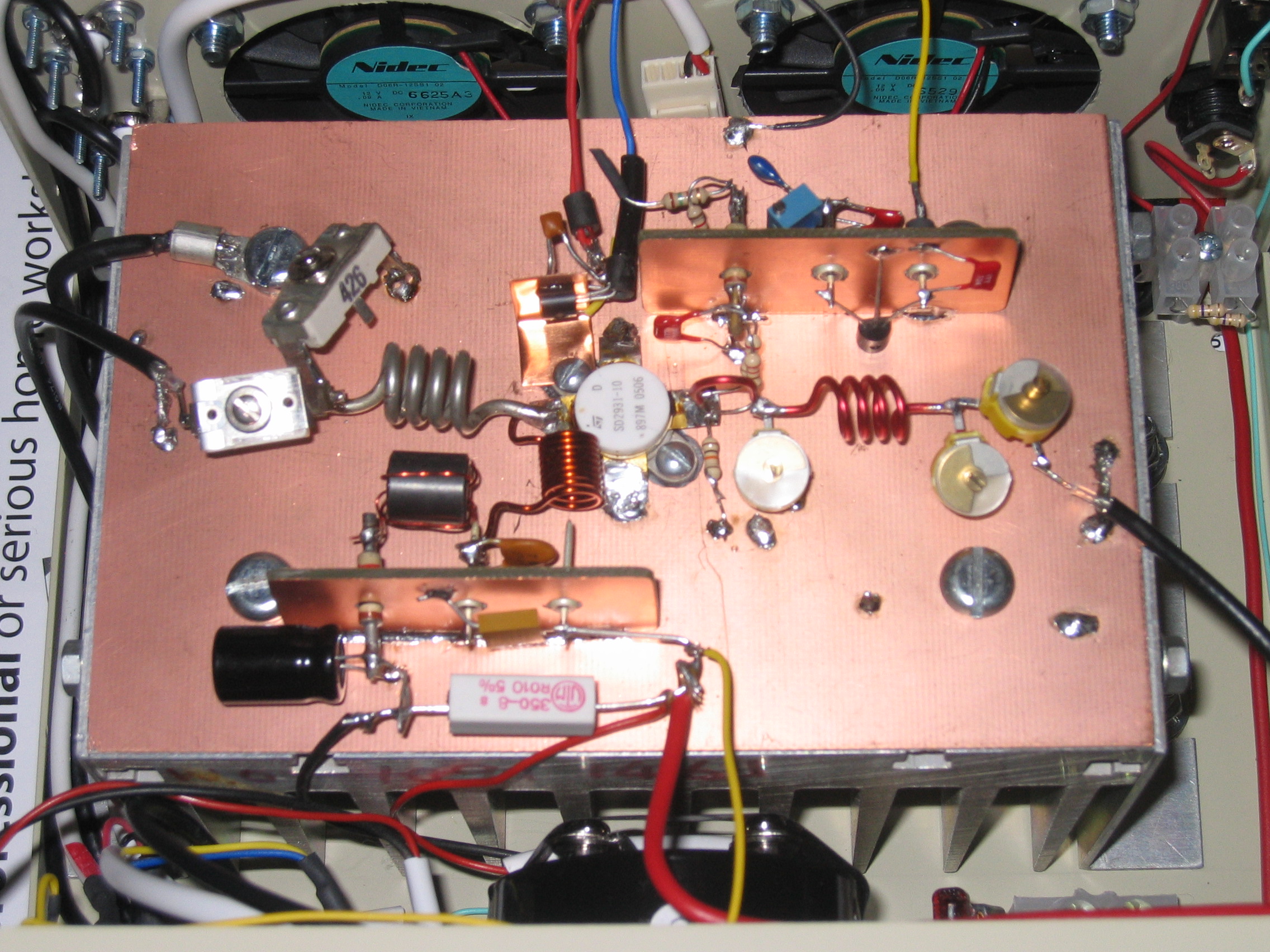
Points to note are the use of mica compression trimmers on the output - there's a lot of rf current flowing in this circuit! I started testing with a 12v supply and once tuned up I moved on to a 50v supply.
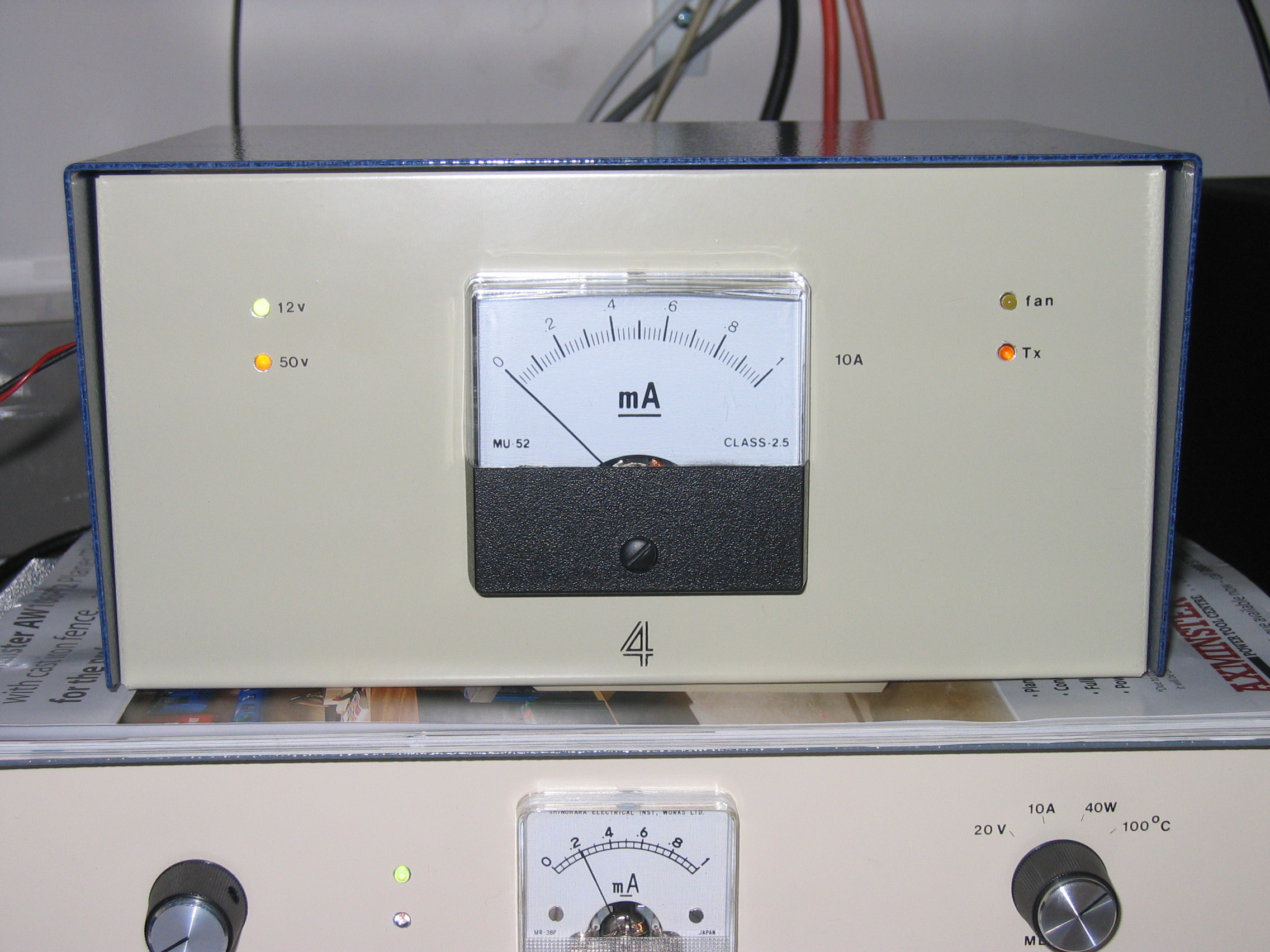
I set the quiescent current Idq = 0.25A. Trimmers now peak in a different place and with 1.4W rf input the PA gives 160W output for 4.64A or 232W dc input and an efficiency of 69%. However, after testing Idq had risen to 0.35A – so there is a need to temperature compensate the bias supply. I incorporated a circuit to allow thermistor control of gate voltage, see the circuit diagram. Idq is then set at 0.25A and drops slightly to 0.24A when hot.
The circuit was amended on 3 Feb 2011 by the addition of decoupling around the 5V regulator which supplies the fan circuit. This suppresses noise which otherwise can be heard in the 4m receiver!
Another point to note when testing PAs like this one is that typical digital multimeters are badly affected by RF. For a reliable indication I had to go back to a moving coil meter! I have also added a circuit for thermostatic control of fans, which are set to switch on at about 40C.
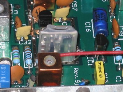
For the antenna change-over relay I used a SDS Relais type S2. This is a small and quiet pc board sealed relay, chosen for its speed (6ms), good hf characteristics and low price. It's available from Barend.
The measured harmonic output is -36dB at 140MHz and <-48dB at 210MHz and above. It is respectable but needs a harmonic filter - the one I built is the coaxial stub filter by G4SWX and is described on the G(M)3SEK website (Look for "Filters: Harmonic notch filters" under "The Best of In Practice"). I measured its performance as follows:-
insertion loss <0.1dB
VSWR <1.1:1
| Freq MHz | Rejection dB |
| 140 | 50 |
| 210 | 47 |
| 280 | 52 |
| 350 | 30 |
| 420 | 40 |
| 490 | 27 |
Further observations shortly.....
Operating cross band - a 6m bandstop filter
In trying to operate cross band I found an excessive amount of noise entering the 6m receiver from the 4m transmitter. The noise comes from both the transverter and the PA. To overcome this I designed a bandstop filter to go in the 4m transmitter output feedline. The filter was designed using Elsie, a very useful filter design program. The design is a Chebycheff bandstop filter with series input. Parameters are 10MHz bandwidth, order 3, 0.01dB ripple, centre frequency 50.2MHz. The design is chosen for minimum loss at 70MHz as it needs to be put in the high power output line.
For 19.7nH, use 10mm diam, 15mm long, 2t of 18g
For 837nH, use 10mm diam, 22mm long, 15t of 26g
For 510pF, I used 270pF || 220pF || 20pF ceramic
For 12pF, I used a 30pF trimmer adjusted for null at 50.15MHz
Predicted loss at 70MHz is 0.1dB, actual not measurable
Predicted loss at 50-50.5MHz is >40dB, actual ~30dB
VSWR <1.15:1
.