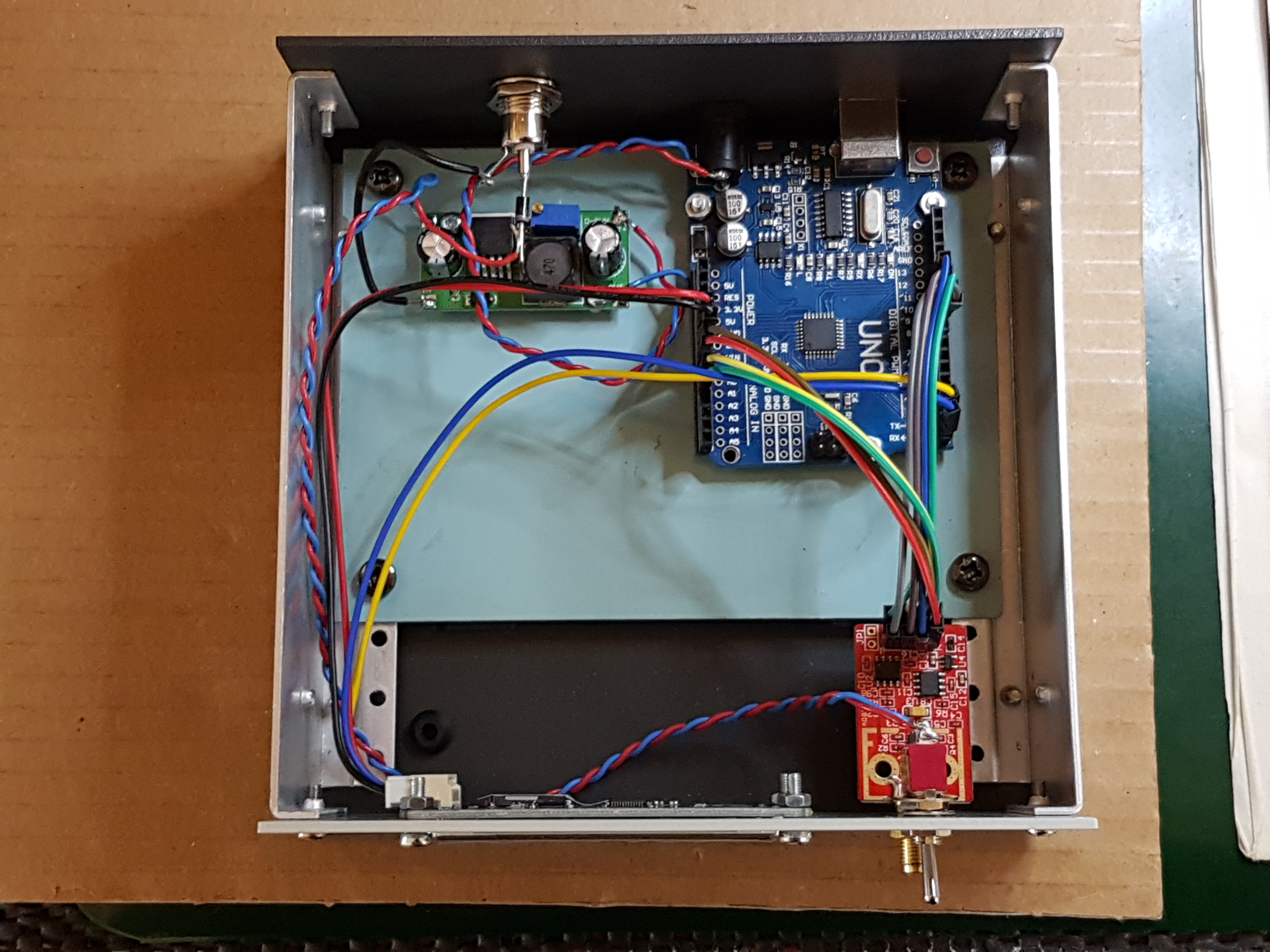
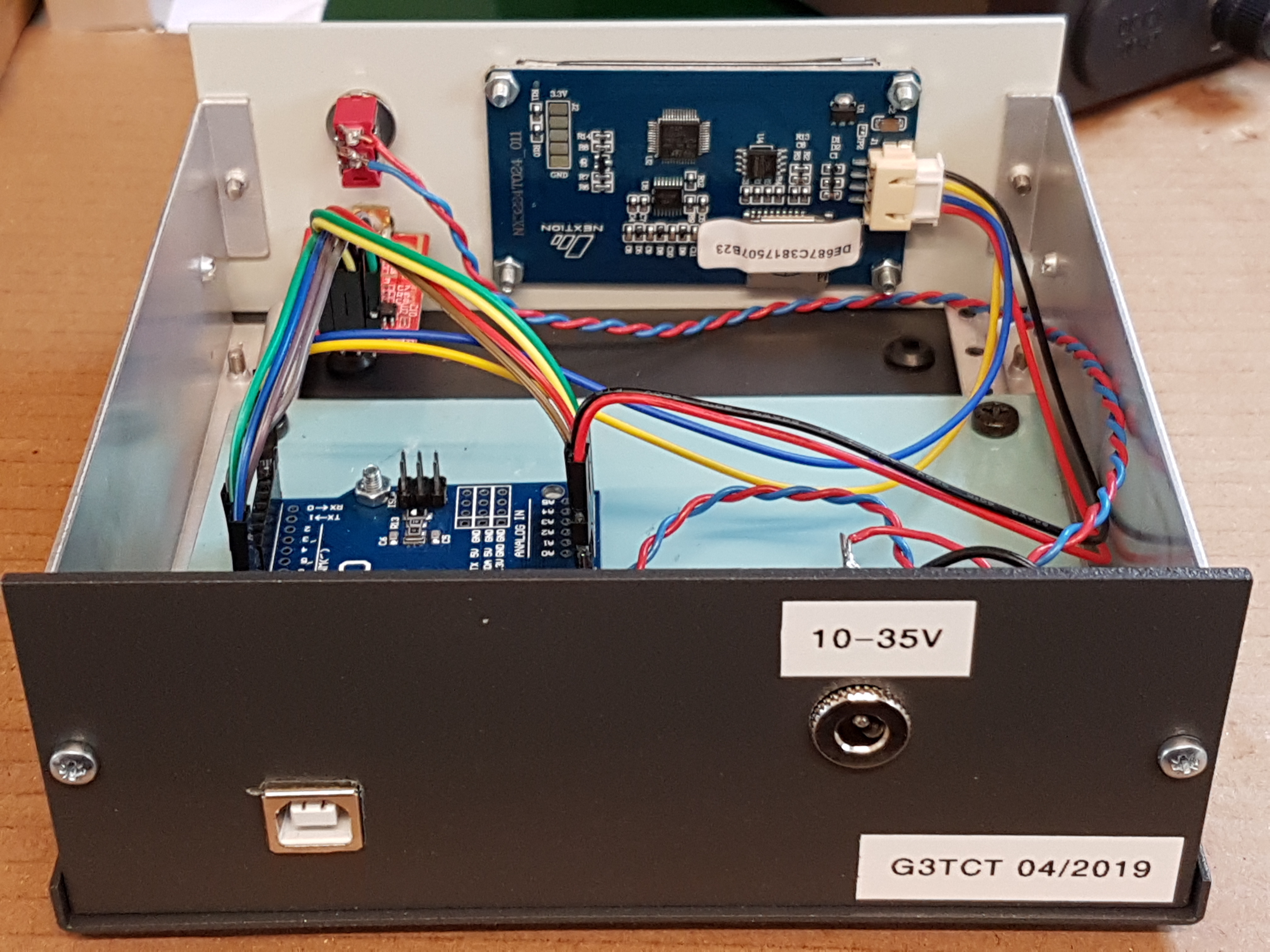
The finished power meter I built looks like this:-

Dietmar DL2SBA has developed Arduino and display code which gives a very attractive result and includes a number of options for external attenuators, calibration at different frequencies, peak readings and backlight control - an impressive project.
Key references are:-
SV1AFN - AD8318 power detector. See his video at the bottom of the page.
DL2SBA - design and s/w
F6ITU - calibration detail
DL2SBA - design and s/w
F6ITU - calibration detail
Suppliers
Apart from the power detector, the other components needed are:-
a standard Nextion 2.4inch touch screen display, which has a very nice development environment, eg from eBay
an Arduino Uno (or Nano would probably work also)
an adjustable power supply, eg this one
an aluminium enclosure - eg 150x150x60mm from eBay
nylon screws to secure the Arduino from Modelfixings
an Arduino Uno (or Nano would probably work also)
an adjustable power supply, eg this one
an aluminium enclosure - eg 150x150x60mm from eBay
nylon screws to secure the Arduino from Modelfixings
Construction
I fitted an aluminium base plate inside the case. This facilitates mounting the Arduino and psu and the underside can be accessed by removing the bottom of the case.
I fitted a 1N4001 diode in series with the power supply to avoid accidents.
Calibration
The detailed method is given by F6ITU. It requires a properly calibrated signal generator. Readings are made of raw data values at a number of frequencies and signal levels. The calibration data provided by DL2SBA is for his implementation which may well differ from mine (and yours). The raw data doesn't reflect the calibration data, so allows new data to be created.
Page created 07/05/2019